Efficient system development with hardware-in-the-loop techniques

Hardware-in-the-loop (HiL) simulation is a proven method in research and industry for testing complex mechatronic systems in real time under realistic conditions. The basic idea of HiL simulation is to analyse a real subsystem in the laboratory (test specimen), which is linked to a virtual image of its environment via actuator and sensor interfaces. The environment model is simulated by a real-time computer. The HiL simulation thus allows the simulation and analysis of a complete mechatronic system, taking into account the interaction of all its components.
Nowadays, mechatronic systems are characterised by a large number of subcomponents and complex, intelligent control systems. Examples can be found above all in the automotive sector. For example, vehicles are equipped with active axles in order to find the best possible compromise between driving dynamics, driving comfort and safety. The increasing complexity of mechatronic systems requires suitable test bench technology.
One of the core competencies of the Control Engineering and Mechatronics specialist group is the development of such complex HiL test benches, whereby the focus is on the realistic simulation of dynamic behaviour. In this context, suitable manipulators must be developed to utilise the full potential of HiL simulation, which allow spatial, highly dynamic and precise excitation of the test specimen. This includes in particular the holistic development, i.e. the development and design of actuators, sensors and non-linear control methods for hydraulic or pneumatic manipulators.
An important demonstrator for our research work is the HiL axle test rig developed in the Control Engineering and Mechatronics workgroup. HiL axle test rig.
Within the field of HiL simulation, we focus on the following research areas:
Demonstrator: HiL axle test with hydraulic hexapod
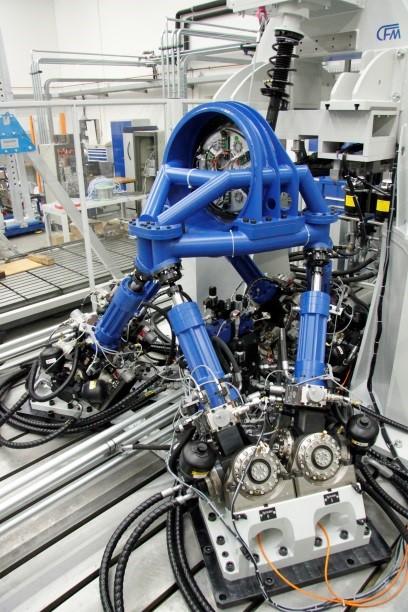
An important demonstrator for our research work is the HiL axle test rig developed in the Control Engineering and Mechatronics workgroup. This enables the simulation of road excitations in all spatial degrees of freedom under real-time conditions. Among other things, a highly dynamically controlled hexapod is used as an excitation unit. To simulate an entire vehicle in a HiL simulation, models of the remaining subsystems, such as wheels, road and vehicle, are simulated in parallel on the real-time computer. The test bench is controlled via a real-time system whose calculations are performed in an 8 kHz cycle. For the hexapod alone, the test bench has six displacement and six pressure sensors, an angle sensor, twelve valve spool displacement sensors and a force measuring wheel that measures the forces and torques at the contact point between the hexapod and the axle. The six control voltages for the servo valves are output.
Hydraulic Hexapod
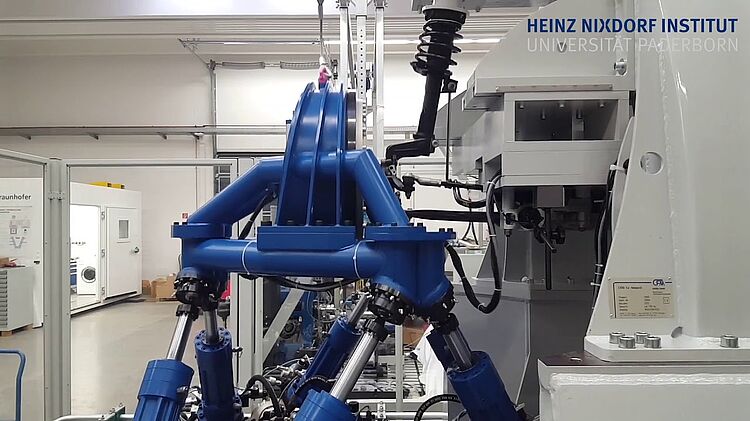
A hydraulic hexapod is also used as an excitation unit for the HiL axle test stand. Hexapods belong to the class of so-called parallel kinematics. In serial kinematics, e.g. a conventional industrial robot, the movement of the tool or - more generally - the so-called end effector results from a sequence of rotations and displacements of individual drives, which can usually also be easily followed with the eye. In contrast, all drives of a parallel kinematic system are attached directly to the end effector. The movement of the end effector no longer results from a sequence of individual partial movements, but is the result of a complex, simultaneous movement of several drive units.
The hexapod is actuated by six hydraulic cylinders. Each hydraulic cylinder of the Hexapod is connected to the base plate at its lower end via a universal joint with integrated oil supply. There is a ball joint at the upper end of each cylinder, via which the cylinders are connected to the working platform of the Hexapod. This arrangement allows the end effector to be moved in all six spatial degrees of freedom.
The video shows the vehicle axle test stand tracing a measured signal from driving over a poor road surface, as is also used in the fatigue strength testing of axles.